Harmonic Solution Guide
A brief history of electric power supply
A brief history of electric power supply
In order to understand why there is a need for a harmonic solution guide, we need to move back to the end of the 19th century, when increasing demand of electricity led to a requirement of public power supply. The conflict between the two concepts “AC” and “DC” lead to the “war of currents” around 1890. Both technologies were promoted and installed, but finally the “war” was won by the supporter of the alternating current technology, against the supporter of the direct current led by Thomas A. Edison. The victory was mainly secured by the ability to transmit energy over long distances by using transformers. Recognizing the advantage of the alternating current George Westinghouse bought patent rights of the transformer (1885 called “secondary generator”) from Lucien Gaulard and John Gibbs and the victory of the AC current took its course.
During the “war of currents” the purpose of electricity was mainly supplying linear loads such as lightning and simple electrical machines, therefore the disadvantages of the AC current had not been predictable. With the worldwide rapidly raising increase of semiconductor and other non-linear loads we are now facing the challenge to keep our AC supply clean, or at least as clean as necessary.
Electrical loads where the current is not proportional to the voltage are called non-linear loads. Linear loads are pure sinusoidal, and either resistive, inductive or capacitive. To verify the difference between linear and non-linear loads, please refer to the picture below.


The loads such as seen in picture 1.2 and 1.3 are pure sinusoidal, at least in this simplified graph. Based on this it is common practice to define the power-factor as the phase relationship between voltage and current, although this is in fact the displacement factor. Therefore literature often refers to the power factor as the “true power factor” in order to avoid misunderstanding.
The definition of (true) power factor and displacement factor are: (v1 and i1 are referring to fundamental frequency)
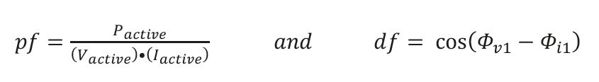
pf and df may have the same value under the condition that all items are purely sinusoidal. In a real application this does not take place which will be explained deeper later on. Continuing the wrong usage of pf for df, lead to so called power factor correction equipment (PFC). As this PFC only focuses on phase correction it will not solve problems related to other kind of distortion. Basically there are different distortions of the mains supply such as:
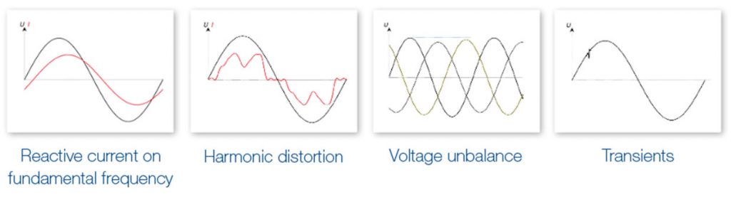
This paper focuses on harmonic distortion, especially the distortion caused by variable frequency drives. Measures for harmonic mitigation usually have a positive impact on other kind of distortion as well.
Ideally all loads and sources have a pure sinusoidal current waveform. But unfortunately the true waveform of most equipment is very different. Non-linear loads like the input current of a standard 6-pulse variable frequency drive (as seen in picture 1.4) are causing a distortion of the mains voltage. This distortion is typically evaluated by the Total Harmonic Distortion THD. For power equipment this THD usually obtains frequencies from the 2nd up to the 40th harmonic. Mathematically the harmonics are not limited to the 40th and for other subjects, e.g. audio equipment distortion; the THD range definition might be different.
In order to evaluate the harmonic distortion we need to understand harmonics from a mathematical point of view: Harmonics are multiples of the fundamental frequency (nth Harmonic = n • f).
For the most common domestic power supply of 50Hz this means:
| 2nd Harmonic = 100Hz | 7th Harmonic. = 350Hz | 12th Harmonic = 600Hz | 17th Harmonic = 850Hz |
| 3rd Harmonic = 150Hz | 8th Harmonic = 400Hz | 13th Harmonic = 650Hz | 18th Harmonic = 900Hz |
| 4th Harmonic = 200Hz | 9th Harmonic = 450Hz | 14th Harmonic = 700Hz | 19th Harmonic = 950Hz |
| 5th Harmonic = 250Hz | 10th Harmonic. = 500Hz | 15th Harmonic= 750Hz | 20th Harmonic = 1000Hz |
| 6th Harmonic = 300Hz | 11th Harmonic = 550Hz | 16th Harmonic = 800Hz | … |
Die Fourier-Transformation zerlegt eine Funktion der Zeit in ihre einzelnen Frequenzen. Dies bedeutet, dass jedes periodische Signal eine Funktion ist, die in einzelne Oberschwingungen unterteilt werden kann. Die nachstehende Tabelle hilft, das Prinzip zu verifizieren.
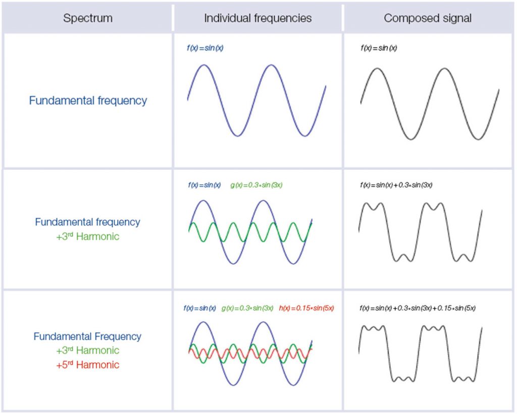
This means from a mathematical point of view it is possible to create any periodical signal by adding up harmonics of different order, phase and amplitude.
If you consider to learn more about maths, please visit:
www.electronics-tutorials.ws
As seen in picture 1.4 the input-current-shape of a standard DC-choked drive is far away from sinus and the input current of drives with AC-choke is largely similar. The input-current-shape of a drive without any inductance is significantly worse. Although there are many different sources of harmonic distortion, a great part is caused by variable frequency drives (VFD). Therefore these pages are focusing on solutions for drives.
When speaking about harmonics in a context of electrical power supply and electrical equipment, this is related to the harmonic distortion between 2nd and 40th Harmonic (in a 50Hz supply this is equal to 100Hz – 2kHz). This frequency range is subject to different standards and harmonics recommendations and the standards are likely to be extended to the frequency of 2kHz to 9kHz very soon.
In a completely symmetrical three phase supply a 6-pulse rectifier input do not cause any distortion on the harmonics that are multiples of 3, nor any distortion on the even number harmonics. In the area of 2nd – 40th this excludes every harmonic except for the following twelve: 5th, 7th, 11th, 13tth, 17th, 19th, 23rd, 25th, 29th, 31st, 35th, 37th. This is the reason why standards and recommendations pay attention to these individual harmonic orders. Of course no true power supply is completely symmetrical; therefore harmonics are also caused on other harmonic orders.
The harmonic distortion is evaluated by the Total Harmonic Distortion (THD) or Total Demand Distortion (TDD) which is each separated for current and for voltage distortion.
The THDi Total Harmonic Distortion of the current is the most used evaluation for equipment. The calculation is considering the sum of all harmonic currents up to the 40th.
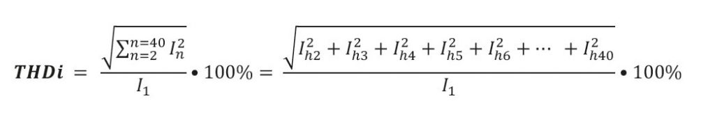
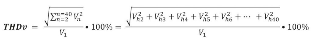
This evaluation is used for many standards and is basically showing the harmonic currents in relation to the fundamental current. The voltage distortion is called THDv and the calculation is very similar using the individual voltage harmonics instead of the current.
Basically the THD is a good evaluation for Harmonic Distortion but it is not sufficient to give a full evaluation of the problems that may be caused by harmonics. One main reason for this is very simple and based on the following correlations for Inductance:

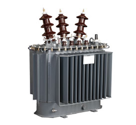
The impedance of an inductance depends on the frequency. This means: higher power losses for higher frequency components. Therefore equipment like transformer and other inductances are sensible to high order components. This is the reason why high harmonic distortion may cause overload on transformer, even though the actual nominal power is far below nominal power of the transformer.
This correlation also shows that the THD does not give sufficient description of the effects caused by harmonic currents. E.g.: If we compare a 100A distortion on the 5th Harmonic (I5=100A) with a 100A distortion on the 37th Harmonic (I37=100A), these currents will cause the same effect on the THDi value. But the power loss inside a transformer caused by I37 would be significantly higher due to the higher impedance on this frequency.
Typically the distortion from equipment is lower on the higher harmonics. Nevertheless this is the reason why standards and recommendation not only pay attention to the THD but also to individual numbers and higher harmonics. A common evaluation for higher harmonics is the Partial Weighted Harmonic Distortion PWHD which is used in different standards and recommendations to evaluate the higher harmonics, in this case all harmonics from the 14th to the 40th.
The following calculation shows the calculation of the PWHD of the current; the calculation for voltage distortion is equal but obviously refers to the individual harmonic voltage amplitude.

These harmonic evaluations THD and PWHD are used in most common standards, especially in different parts of the IEC 61000 and EN 50160.
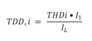
The standard IEEE 519-2014 is the recommended practice and requirement for harmonic control in electric power systems. This standard gives recommended practice how to deal with harmonic distortion and uses a slightly different evaluation of the harmonic currents:

On the first sight this equation might appear equal to the THDi, the difference is the denominator, and use IL instead of I1. Both IL and I1 are defined as the fundamental current, or “1st Harmonic” so typically 50Hz or 60Hz. The I1 is the fundamental current for each individual operating point but IL is defined by the IEEEE as: “This current value can be established at the PCC and should be taken as the sum of the currents corresponding to the maximum demand during each of the twelve previous months divided by 12.“ Due to occasional overload of the systems this usually results in lower TDD values at nominal load compared to the THDi but especially in part load this leads to significant lower values (see Diagram 1).
The voltage distortion is caused by the amplitude of the individual harmonic currents not by the percentage value of the actual operation point. VFD equipment show increasing harmonic currents with increasing load therefore the TDD gives more accurate information about the effect on the mains supply.
The following diagram is showing the correlation between TDD and THDi and the values of a VFD with a Passive Harmonic Filter input.
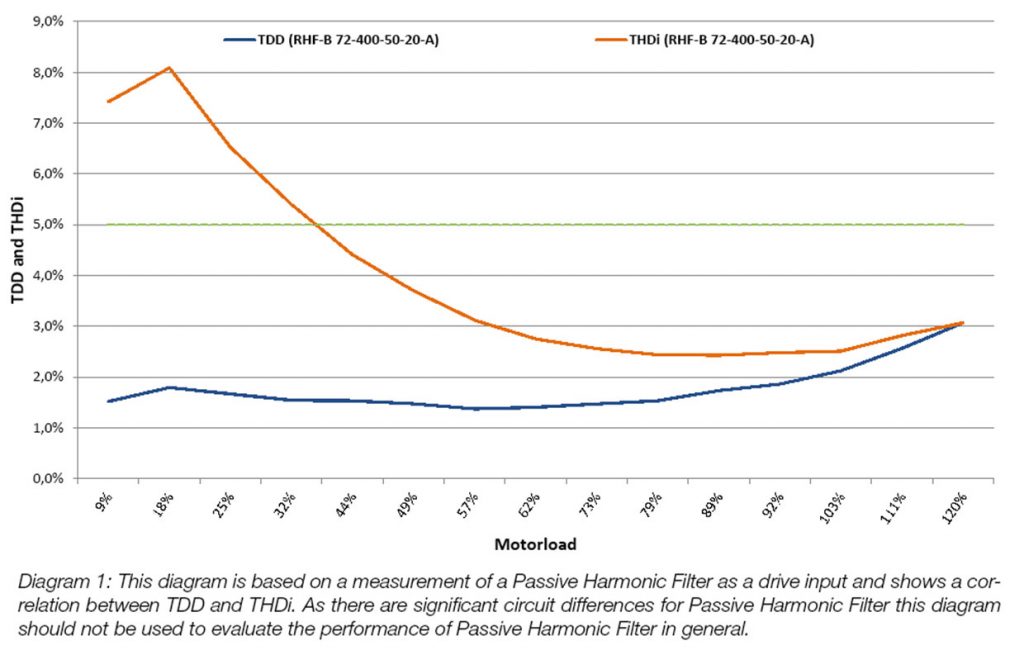
Imagine the above diagram showing only the THDi. An inexperienced user might now assume that the harmonic distortion is worst at 18% motor load. The TDD curve is showing that the worst distortion is at 120% load. This is why the TDD is a more user-friendly way to evaluate or specify the harmonic distortion in a specific system.
The measurement of harmonic components is very complex but quality measurement equipment such as power analyzer are able to measure the harmonic component and show you THDi and THDv values, some equipment also show you the PWHD values. However the measurement equipment typically cannot know the IL as defined by the IEEE therefore common power analyzer are not able to show the TDD. If you are able to evaluate the IL you can calculate the TDD from any operating point and the corresponding THDi and I1 value.
However, these evaluations are only for interest or if user would like to check if the equipment provider is meeting the stated values. Basically the TDD is always lower than the THDi value.
Basically the distortion of the current is not a significant problem for the equipment (VFD) itself but the non-sinusoidal current is causing a distortion of the sinusoidal mains supply. This distortion of the mains supply affects the connected equipment. The impact of the voltage distortion is diverse and the most typical effect is overheating of transformer and PFC applications (capacitor banks). An underestimated impact of harmonic distortion is the significantly reduced lifetime expectation of electrical and mechanical equipment.
The most common problems related to harmonic distortion are listed below:
 Transformers and PFC
Increased losses on inductances:

(↑ frequency = ↑ Impedance)
Reduced power! Expected lifetime lower! Less efficiency!
Transformers and capacitor banks must be oversized or might overheat at nominal load.
Electronical equipment
Increased losses and reduced lifetime expectation.
Equipment failures → Lost data, Production loss, Equipment costs
Wrong evaluation of signals → troubleshooting costs and production loss
Motors and Generators (uncontrolled)
Increased losses and reduced lifetime expectation.
Reduced torque and unsteady torque (even vibrations) on shaft output. Lower lifetime expectations of bearings, gearboxes and further connected equipment.

System Efficiency
Equipment efficiency may be affected by the harmonic distortion of the mains voltage. In addition connection wires will produce higher losses. This leads to higher costs for user.
Harmonic mitigation equipment is basically divided into two different segments: Passive and active solutions.
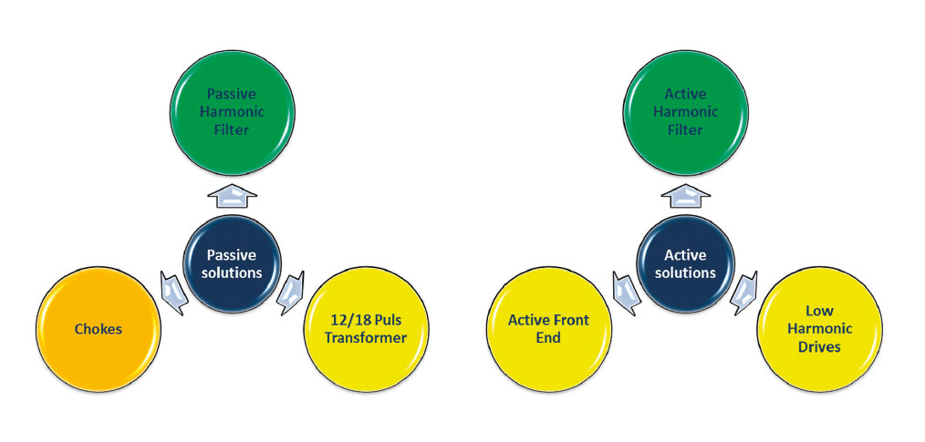
The most basic passive solution for harmonic mitigation is a AC or DC choke (inductance), typically the drive manufacturers already have this installed or at least specify which inductance must be installed (typically 2-4%). The performance of a choke in this setup is limited (~35-45% THDi) therefore this paper will consider a choke as minimum and focus on solution for <10% THDi. True passive solutions include circuits of L and C (and unfortunately sometimes also R). Quality and performance is very different depending on used brand.
Active solutions contain: active input circuits combined with LCL filter and parallel active harmonic filter.
From a hardware point of view Active Front End (AFE) and Low Harmonic Drives (LHD) are usually equal. The AFE technology gives you the advantage or regenerating energy when the motor is operating as a generator. As this function is obviously useless for simple installations as pumps and fans the same hardware is promoted as LHD where now the regen function is disabled.
In fact the “Low Harmonic Drive” is specified different by different brands. Some manufacturer refers to this as a standard inverter with an internal inductance, others use internal passive filter. Therefore when comparing LHD´s it´s necessary to pay attention to the internal setup and the resulting THDi.
The following picture shows a simplified setup of the most common solutions for harmonic mitigation and the typical resulting THDi performance.
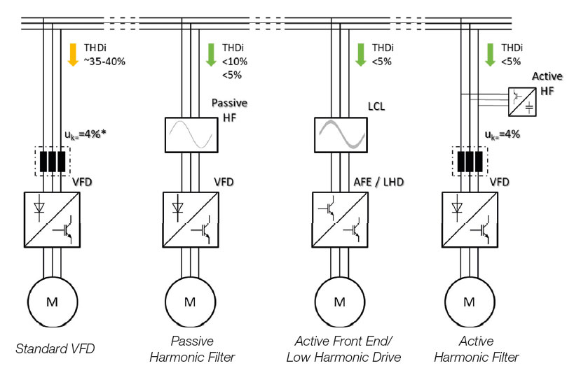
Passive Harmonic Filters are different circuits of L and C and unfortunately sometimes also R. Quality and performance highly depend on the used brand. Harmonic performance values <3% THDi are possible although these cannot be guaranteed. Typical stated performance is <5% or <10% THDi. Passive Harmonic Filters are very simple and are usually the most suitable choice for harmonic mitigation. Nevertheless, there are significant differences depending on the internal setup. Therefore it´s essential pay special attention to the following characteristics:
1. Efficiency (this should be as high as possible: for >100A at least 99% efficiency).
2. DC-Voltage Drop (the filter should not cause a voltage drop on the DC Bus at nominal load
(if it does this can be compensated by using a drive with higher current rating)).
3. Performance conditions (please make sure the stated performance is reached under
realistic conditions, some PHF define <5% THDi but only on an ideal network).
Active Front End and Low Harmonic Drives are equipment with IGBT input. This active input allows the application to limit the harmonics on the input current and therefore allow an almost sinusoidal current waveform. Different brands reach different performance but basically a THDi of 3-5% can be reached. This technology is always combined with an LCL filter component.
Unfortunately the high switching frequency of this technology brings two significant disadvantages:
1. The efficiency of the system is significantly worse than other solutions (typically 1-3% higher losses).
2. The technology brings a clean signal on the harmonics up to 40th but it will also
cause a new distortion on higher harmonics, typically in the harmonic area from
the 50th to 200th (The distortion in this frequency band is causing problems already
and is going to be regulated by international standards soon).
Based on these disadvantages it is not recommended to use this technology for harmonic mitigation.
Some drive manufacturer has recognized these disadvantages and uses active or passive harmonic filter internally, still calling the solution a Low Harmonic Drive. These solutions are recommended; therefore it is essential to pay attention to the internal setup of a “Low Harmonic Drive”.
Active Harmonic Filters are parallel filter circuits injecting harmonics into the supply. These Harmonics have phase shift of 180° compared to the harmonics in the system. Therefore the injected Harmonics are eliminating the Harmonics seen from the mains supply. The following picture helps to verify the principle.
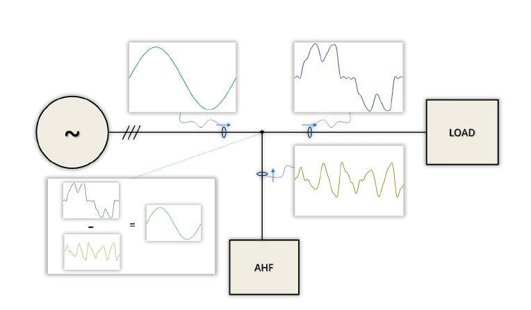
When using a high quality active filter the efficiency of the filter is typically around 97%. On the first sight this might appear low but for the system this means that it is almost as good as a high efficiency passive harmonic filter, the reason for this lies in the topology: Assuming a load of 1000A with a THDi of 35%, this results in a harmonic current of 1000A • 35% = 350A (simplified estimation of harmonic current). This means that the Active Harmonic Filter needs to be sized only for 350A. Passive Harmonic Filter and Active Front End technology are sized for full load current of 1000A. Assuming a THDi of 35% this results in load based efficiency of ~99%.
The investment for an active filter solution is typically higher than for passive filter solution but placing one central active filter, instead of many small passive filters might be the right choice after considering all installation costs. Therefore there is no “best solution” when comparing Active Harmonic Filter and Passive Harmonic Filter (as long as we compare high efficient and high quality products). The right choice depends on the system.
Distributors and companies offering both Active and Passive Harmonic Filter are able to give a selfless recommendation on this choice. In addition they will be able to offer a combination of both technologies which is often the best technical and commercial solution.
In terms of harmonic distortion the limits provided by the electricity supply authority are quite high (depending on area). Therefore it is recommended to use the IEEE 519-2014 as a reference for power quality. This recommendation gives a very good guideline and makes sure the distortion of the supply is limited reasonable. For systems with many drives it is recommended to use the following sentence:
“The System shall meet all requirement stated under latest edition of IEEE 519 Harmonic Guidelines.”
Basically you can state the IEEE 519 for each individual drive but this might exclude the best possible solution as each VSD needs individual harmonic filter. Especially systems combining small and big drives benefit from the combination of Passive and Active Harmonic Filter, as it allows to ignore smaller filter and use a high quality filter for the higher power rating. This may give you the same or even better total performance than using a low quality harmonic filter for every individual drive.
For applications with a high duty e.g. HVAC industry it is essential not only to specify the harmonic performance but also the efficiency of the harmonic solution. Therefore the following sentences can be added to a tender:
Harmonic solutions for VSD´s with a nominal input current <100A shall have an efficiency of >98%.
Harmonic solutions for VSD´s with a nominal input current > 100A shall have an efficiency of >99%.
The Harmonic solution shall not affect the efficiency of the VSD by DC-bus voltage fluctuation.
As the quality standards of the different brands are very different it is recommended to use manufacturer who offers a extended warranty in accordance to your requirement. The design life of a passive filter should be at least 10-15 years.
In addition it is recommended to state the available short circuit power of the connection point (see following chapter). If this is not provided the lowest short circuit power ratio will be assumed and therefore the costs might be higher than necessary.
The harmonic currents of individual equipment cause harmonic distortion on the mains voltage. The reason for this is too complex for this paper but basically it is important to know that a harmonic current of equal size will cause different harmonic distortion on the voltage depending on its impedance. Imagine an unloaded generator of 100kVA with a 2% THDv pre-distortion: If you connect a VSD with a 35% THDi to this the result will be a distortion on the voltage e.g. 3% THDv (results obviously depend on VSD size).
Now Imagine the same VSD connected to a 200kVA generator with the same 2% THDv pre-distortion: The resulting THDv would be much better (somewhere between 2% and 3%). The true calculation is significantly more complex but the essence of this is: If your mains supply is “week”, the effect on the THDv caused by the harmonic current is higher than in a “strong” network.
Now obviously “strong” and “week” are not precise information therefore standards refer to the ratio of short circuit power to connected power which is evaluating the strength of the supply. In the IEEE 519-2014 you will find the following table:
| Maximum Harmonic Current Distortion in Percent of IL | ||||||
| Individual Harmonic Order (Odd Harmonics) | ||||||
| ISC /IL | <11 | 11≤h<17 | 17≤h<23 | 23≤h<35 | 35<h | TDD |
| <20 | 4.0 | 2.0 | 1.5 | 0.6 | 0.3 | 5.0 |
| 20<50 | 7.0 | 3.5 | 2.5 | 1.0 | 0.5 | 8.0 |
| 50<100 | 10.0 | 4.5 | 4.0 | 1.5 | 0.7 | 12.0 |
| 100<1000 | 12.0 | 5.5 | 5.0 | 2.0 | 1.0 | 15.0 |
| >1000 | 15.0 | 7.0 | 6.0 | 2.5 | 1.4 | 20.0 |
The required harmonic performance level is lower for a lower ratio of short circuit current to maximum load current. Standards such as IEC 61000 are using the slightly different evaluation called the RSCE

If this ratio remains unknown the lowest possible ratio must be assumed. This might increase the investment for harmonic mitigation equipment. Whilst Sequ is normally known (this is equipment input power) the calculation of SSC is a bit more complex.
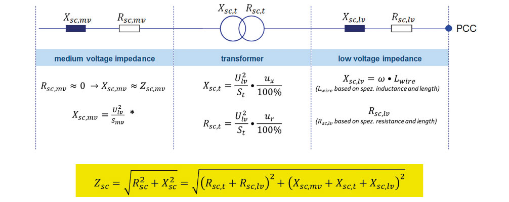
The missing value to solve the evaluation is ZSC which is the impedance of the mains. Basically the supply authority should be able to provide you information on the connection point. In addition you need information about the transformer and installed wire lengths used.
For short low voltage cable length and a strong medium voltage supply, the total supply impedance ZSC can be assumed as the transformer impedance. This is usually given by the short circuit impedance uk. E.g. Transformer: uk = 4.1%, ST = 1 000kVA

This calculation should be used with caution as low medium voltage impedance and long distance wires (or low cross-section) may affect the short circuit power significant!
The object of this guide is to give a brief introduction into the topics of harmonic disturbances; therefore some topics are simplified in order to support basic understanding. This is the first edition of this guide and corrections or suggestions may be sent at info@revcon.de.
REVCON is a medium sized company located in the western part of Germany. Since more than two decades REVCON has been active in the field of drive engineering and stands for innovation, versatility and high performance.
The REVCON products are universal Plug & Play solutions; the extensive product portfolio covers:
• High efficient Passive Harmonic Filter
• Active Harmonic Filter
• Regenerative Units
• Front Ends (regen)
• Front Ends (non-regen)
• DC-DC and AC-DC converter
• Power quality services such as advanced harmonic analysis
• At last but not at least: customized solutions!
Our components are used in many different applications in drive engineering and automation as well as in the renewable energy sector; for example in hoisting and conveyor systems, the elevator industry, in engine test stands, escalators and wind parks. Our passive harmonic filter RHF is the leading brand on the market and is used in various HVAC applications around the world.
REVCON is cooperating with all mayor drive brands and products can be REVCON labeled or brand-labeled. Beside a very reliable and easy setup the main advantage of REVCON is their ability to adapt their products into the needs of the customer while still providing a competitive price!
Your contact person Mr. Martin Elvhage,

can be reached at: +49 (0)2383 920 22 32
or send your enquiry by e-mail
to: m.elvhage@revcon.de

Dipl.-Ing. Frank Rambuscheck
Techn. Geschäftsführer
Tel: +49(0) 2383/92022-22
E-Mail: F.Rambuscheck@revcon.de

Mareike Hrubesch-Fondacaro
Kfm. Geschäftsführerin
Tel: +49(0) 2383/92022-22
E-Mail: M.Hrubesch-Fondacaro@revcon.de

Markus Damasch
Geschäftsleitung Projekte
Prokurist
Tel: +49(0) 2383/92022-19
E-Mail: M.Damasch@revcon.de
Martin Elvhage, B. Eng.
Business Development Manager – Applikationsberatung
Tel: +49(0) 2383/92022-32
E-Mail: M.Elvhage@revcon.de

Stanley Ng
Managing Director (APAC)
Stanley@revcon.com.sg
+6562660523

Beaujolais Ng
Technical Engineer - Responsible for technical questions
beaujolais@revcon.com.sg
+6562660523
Beacher Ng
Account Admin Assistant – Responsible for offer and accounts
beacher@revcon.com.sg
+6562660523
Bitte füllen Sie die mit einem einem Stern * markierten Felder aus.
Error: Contact form not found.
Bitte füllen Sie die mit einem einem Stern * markierten Felder aus.
Error: Contact form not found.
Bitte füllen Sie die mit einem einem Stern * markierten Felder aus.
Bitte füllen Sie die mit einem einem Stern * markierten Felder aus.
Ihren Ansprechpartner Herrn Martin Elvhage, Error: Contact form not found.
erreichen Sie unter: +49 (0)2383 920 22 32
oder schicken Sie Ihre Anfrage per E-Mail
an: m.elvhage@revcon.de
Your contact person Mr. Martin Elvhage,
can be reached at: +49 (0)2383 920 22 32
or send your enquiry by e-mail
to: m.elvhage@revcon.de
睿康电气(深圳)有限公司 A5 Building, First industry zone, Xiashiwei village, Bao'an, Shenzhen, 518000, PRC